Firewall system #
The LionsOS project contains an example system that acts as a firewall between networks. Each network interface of the firewall system has its own instance of an sDDF net subsystem. The firewall multiplexes incoming traffic based on its protocol, and permits or denies the traffic based on a set of build and run-time configurable rules. The firewall also acts as a router and can forward traffic to its next-hop based on a build and run-time configurable routing table. There are further networking functionalities the firewall is capable of detailed below. The firewall example is currently fairly rudimentary, and we invite the community to help complete it. A list of issues and missing features of the firewall can be found here.
This page describes the system’s architecture and details how it works, if you are interested in building, running or testing it see the pages on:
Supported platforms #
The system currently works on the following platforms, although we hope to expand this in the future:
- QEMU virt AArch64
- Compulab IOT-GATE-IMX8PLUS
The simplest way to get started with testing and developing the firewall is to run it on QEMU inside our custom ubuntu Docker container, which emulates the required network infrastructure. Instructions on setting up the container can be found in the section on running on QEMU inside Docker.
If you are are using real hardware to test the firewall system, you will need to configure subnets and hosts for each network interface. More details on this can be found in the section on running on hardware.
Architecture #
Below is a diagram of the architecture of the firewall system containing all the components. Components with arrows are connected via a Microkit Channel and shared memory, holding some type of sDDF or firewall queue data structure.
Currently, the firewall example only supports two network interfaces (NICs), one denoted by external (untrusted, referred to as 0), the other internal (trusted, referred to as 1). We hope to support a variable number in the future. The webserver component, which is used to view and modify filtering rules and routes, is currently only reachable from the internal network.

Firewall Shared Memory Regions #
The firewall implements zero-copy forwarding of packets from reception to transmission. This requires that the receive DMA region of one NIC be a transmit DMA region of the other. Additionally, each component that generates packets has its own transmit DMA region allocated through the sDDF net sub-system.
Aside from network DMA regions, the majority of other shared memory regions hold single-producer, single-consumer queues. The queue data structures that can be found in the firewall are:
sDDF Net Queues #
An sDDF net queue is really a pair of queues used to transfer receive or transmit data buffers between components. sDDF net queues are used when buffers are to be returned to the same component they are received from. In a typical sDDF net system this is always the case, however the firewall often requires components to return buffers to different components. sDDF net queues also use a signalling protocol to decide when to signal their neighbouring component. More on sDDF net queues can be found here.
Firewall Queues #
A firewall queue is also used to transfer receive or transmit data buffers, however it is only one-way. This allows components like the firewall transmit virtualiser to receive buffers from the router, and return them back to the firewall receive virtualiser upon transmission. Firewall queues, along with all the following queues, do not use a signalling protocol to determine when to signal, and instead components signal their neighbour every time a batch of buffers has been enqueued.
ARP Queues #
An ARP queue is a pair or queues (request and response) holding ARP data, namely IP and MAC addresses, and whether or not an IP is reachable. ARP queues are used by routers, ARP requesters and the webserver to request the MAC address of IPs they wish to transmit to.
ICMP Queues #
ICMP queues are one-way queues used between the routers and the ICMP module to request that an ICMP packet should be sent. Currently the ICMP module has limited functionality, however we hope to expand on this in the future.
Other Shared Memory Structures #
Not pictured in the diagram are the shared memory regions between components without a Microkit Channel, namely the filters connection instances regions shared between pairs of filters of the same protocol.
Firewall Components #
Firewall Network Components #
The firewall network transmit (Tx) and receive (Rx) virtualisers are based on the sDDF network virtualiser components with minimal modifications, as detailed in the sDDF design document. The main modification to both virtualisers is the introduction of firewall queues in addition to sDDF net queues. This alters the flow of control of the virtualisers as both queues need to be handled differently.
Rx Virtualiser #
The Rx virtualiser has additionally been modified to multiplex based on a packet’s Ethernet type or IPv4 protocol number, rather than the sDDF network Rx virtualiser which uses destination MAC address. Packets are forwarded to the corresponding ARP or filter component depending on the match. The following diagram illustrates how the Rx virtualiser is connected to its neighbours which it forwards packets to (not pictured is how buffers are returned to the Rx virtualiser).

As with sDDF network Rx virtualisers, static client queue and protocol
configuration data is generated in the metaprogram and copied into
the .elf file at build time.
ARP Components #
The firewall contains two distinct ARP components per NIC: the ARP responder which simply responds to ARP requests addressed to the firewall, and the more complex ARP requester which is responsible for handling all system ARP requests for local IPs and maintaining ARP tables.
ARP Requester #
The ARP requester receives ARP requests from the router, and in the case of the ARP requester associated with the internal NIC, the webserver component. Requests, and their eventual responses are passed between components in ARP queues. Requests have the following structure:
typedef enum {
    /* entry is not valid */
    ARP_STATE_INVALID = 0,
    /* IP is pending an arp response */
    ARP_STATE_PENDING,
    /* IP is unreachable */
    ARP_STATE_UNREACHABLE,
    /* IP is reachable, MAC address is valid */
    ARP_STATE_REACHABLE
} fw_arp_entry_state_t;

typedef struct fw_arp_request {
    /* IP address */
    uint32_t ip;
    /* MAC address for IP if response and state is valid */
    uint8_t mac_addr[ETH_HWADDR_LEN];
    /* state of arp response */
    uint8_t state;
} fw_arp_request_t;
It is the ARP requesters responsibility to convert this raw ARP request data into a packet and transmit it out the network. Upon response, the requester will insert an ARP entry into the ARP table, which the routing component also has read-only access to. ARP entries have the following structure:
typedef struct fw_arp_entry {
    /* state of this entry */
    uint8_t state;
    /* IP address */
    uint32_t ip;
    /* MAC of IP if IP is reachable */
    uint8_t mac_addr[ETH_HWADDR_LEN];
    /* bitmap of clients that initiated the request */
    uint8_t client;
    /* number of arp requests sent for this IP address */
    uint8_t num_retries;
} fw_arp_entry_t;
If after a configurable timeout a response has not been received, the request will be retransmitted. If a threshold of retries is reached, the IP will be considered unreachable and an unreachable entry will be added to the ARP table.
After a response is received or an IP is deemed unreachable, an ARP response
will be enqueued with the client who originally requested the MAC address. After
a configurable time interval the ARP table is completely flushed to ensure stale
entries are removed. Time intervals and retry limits can be configured in the
arp_requester.c file.
The following diagram shows how the ARP requester is connected to its clients:

ARP Responder #
The ARP responder is a simple component. It requires only a statically defined firewall IP and MAC address (obtained as configuration data generated by the metaprogram) to respond to ARP requests addressed to the firewall. All ARP requests received by the NIC will be routed to the ARP responder, and responses will only be generated if there is a match with the firewall’s local IP.

Filters #
Filter components are responsible for determining whether traffic or a certain IP protocol number should be permitted through the network. They are the first component to receive non-ARP traffic after the network Rx virtualiser. If it is decided that a packet is permitted through the firewall, a filter will transfer the packet to the routing component via a firewall queue. If the packet is not permitted, it will be returned back to the Rx virtualiser. For each supported protocol number, there is one filter per interface. Currently, the firewall contains only ICMP, UDP and TCP filters that share a very similar implementation. We hope to extend our protocol specific filtering for TCP traffic in the future.
To determine whether traffic should be permitted or dropped, filter components
check their filter rules tables. If there is no match, the default rule is
applied. Both the filter rule table and default rule of a filter may be updated
using the webserver GUI. Our current classes of filtering rules
are denoted by fw_action_t and are applied to packets whose source and
destination IP addresses and port numbers match against a fw_rule_t (the most
specific match is applied in the case of multiple matches):
typedef enum {
    /* no rule exists */
    FILTER_ACT_NONE,
    /* allow traffic */
	FILTER_ACT_ALLOW,
    /* drop traffic */
	FILTER_ACT_DROP,
    /* allow traffic, and additionally any return traffic */
    FILTER_ACT_CONNECT,
    /* traffic is return traffic from a connect rule */
    FILTER_ACT_ESTABLISHED
} fw_action_t;

typedef struct fw_rule {
    /* whether this is a valid rule */
    bool valid;
    /* action to be applied to traffic matching rule */
    uint8_t action;
    /* source IP */
    uint32_t src_ip;
    /* destination IP */
    uint32_t dst_ip;
    /* source port number */
    uint16_t src_port;
    /* destination port number */
    uint16_t dst_port;
    /* source subnet, 0 is any IP */
    uint8_t src_subnet;
    /* destination subnet, 0 is any IP */
    uint8_t dst_subnet;
    /* rule applies to any source port */
    bool src_port_any;
    /* rule applies to any destination port */
    bool dst_port_any;
} fw_rule_t;
The allow and drop are self explanatory, while the connect and
established actions are related. If a packet matches with a connect action,
this implies the filter should allow the packet through the firewall, as well
as any return traffic. This is implemented using a pair of shared memory
regions between matching protocol number filters denoted instance regions.
Upon matching with a connect rule, a filter creates a connection instance for
the packet in its instance region. Before filters check their rule table, they
first check their neighbour’s instance table to determine if this is permitted
return traffic allowed by their neighbour. If an instance is found, the
established action is returned and the traffic is permitted. Upon the deletion
of a connect rule, all instances corresponding to that rule are removed.
The following diagram shows the flow of packets through the filters, as well as the shared instances regions between matching filters.

Routing Components #
Currently there are two routing components, one for each NIC (although we hope to change this to one in the future). Routers receive packets which have been allowed through the firewall by the filter components. They are responsible for finding the MAC address of the next-hop of the the packet and updating the Ethernet header.
The first step of this procedure is to look up the destination IP in the routing table, which is partially configured at build time with the metaprogram and can be re-configured at run-time using the webserver component. If multiple matches are found, the more precise match will be selected. If no route is found the packet will be dropped.
If a next-hop IP address is found, the ARP table is searched to find the
corresponding MAC address. If a valid entry is not found, an ARP request is
generated and enqueued with the ARP requester, and the outgoing packet is
enqueued in a pkts_waiting_t linked list grouped by destination IP. If a
valid, reachable entry is found or returned from the ARP requester, the packet
will be updated and transmitted. If the next-hop is found to be unreachable, the
packet will be dropped. When a packet is dropped, the router sends the details
of the packet to the ICMP module so a destination unreachable
packet can be transmitted back to the source IP.
The following diagrams demonstrate the flow of packets through the routers. The first diagram shows the external router, and the second shows the internal. The only difference being that the internal router has a route to transmit to the webserver component.


ICMP module #
Currently the ICMP module’s only functionality is to handle the sending of ICMP
destination unreachable packets back to senders when a route to a host cannot
be found, however we hope to expand this in the
future. Unlike most components,
there is only one ICMP module which is able to transmit out both NICs. The ICMP
module also shares ICMP queues with all components that require the generation
of ICMP packets. The diagram below demonstrates the current connections of the
module.

Webserver #
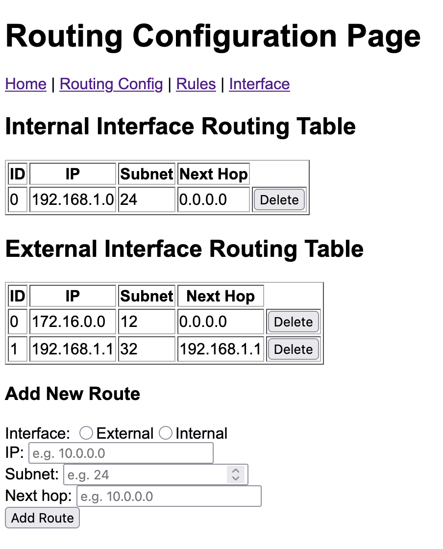
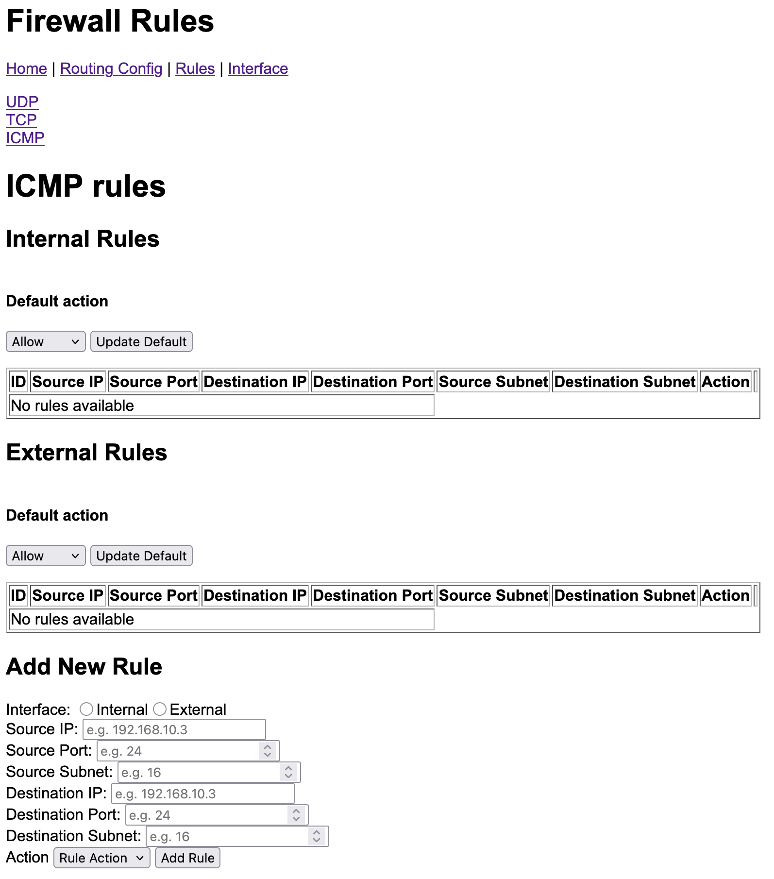
The webserver component provides a basic web GUI for the firewall that can be accessed via the internal network. It is reachable by the firewall’s internal IP address on port 80. Only TCP traffic is currently permitted. The GUI currently displays:
- Network interface details (IP, MAC)
- Filtering rules for each filter and interface
- Routing table of each router
The filtering rules and routing table routes can also be added and removed.
The webserver component is the same Micropython component used in the
webserver example, with slight modifications to how it receives
packets and handles ARP requests.
It utilises the Micropython
Microdot library to host the
website. The front end Micropython code can be found in ui_server.py, and the
back end C module is implemented in modfirewall.c.
The following diagram shows how the webserver is connected to the system:

In contrast to all other connections in the firewall, the webserver uses protected procedure calls (PPCs) to modify the state of filter and routing components. Since it is not anticipated the routes and rules will be updated at a high frequency, this significantly simplifies the interface. The webserver has all filter rules and routing tables mapped into its address space read-only, which allows them to efficiently be displayed without disrupting the flow of traffic through the system. A PPC is only required for modification.
The following images show the GUI pages for viewing and updating routing table routes and the ICMP filter’s rules: